
|
Who doesn't love lasers? Let's do something more than make a dot on the wall with a laser: let's build a communication system for less than Rs 400/- .Safety First: Even before starting this project I want to mention to always be careful with lasers: even a weak laser can cause permanent damage to the human eye in a few seconds. More powerful lasers may cause blindness instantly. Never shine a laser at anybody's face, animals included. If working with a powerful laser, I strongly recommend making a laser lab, and using laser goggles for the frequency of your laser. With that covered, let's move on to what you came here for: a fun, safe project using LASERS! A communication system pretty much always breaks down to two parts, a transmitter and a receiver. Laser communication systems are no different: the laser is the transmitter and for the receiver we will use a photo-resistor. So really it's two circuits. For this project I am going to keep both of them very basic. This means this project could be completed in just one evening, and it's inexpensive. So let's start with the parts list. Parts NeededComponents needed for one channel
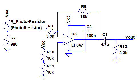
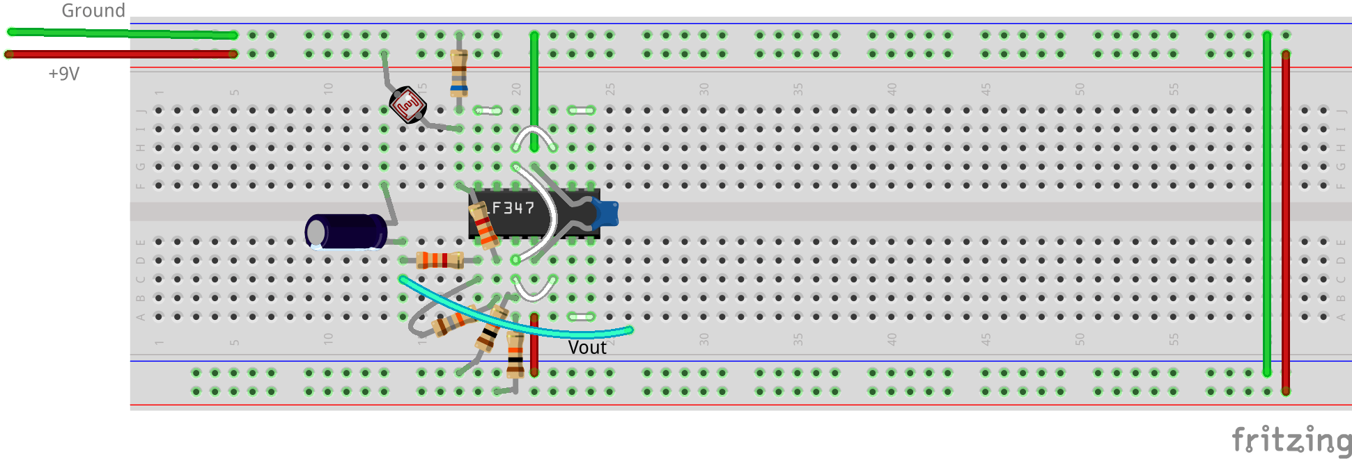
Transmitter DesignBecause I'm sending a continuous analog signal, I will need my laser bias such that the laser is on at all times. If you are sending a digital signal I still recommend this, as some lasers do not like to be pulsed at high frequencies. I am going to bias my laser at 4.5VDC and modulate it from 4V to 5V. First measure the current draw of the laser at 5V, for my laser it was drawing 29mA. This is more than what many op-amps can provide so I will power my laser with a transistor set up as a voltage follower. To drive the voltage follower, I will use a op-amp to mix my input signal with 4.5V and attenuate the signal from 2Vpp to 1Vpp 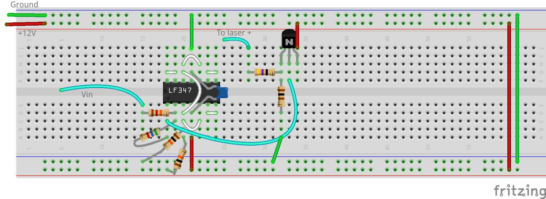 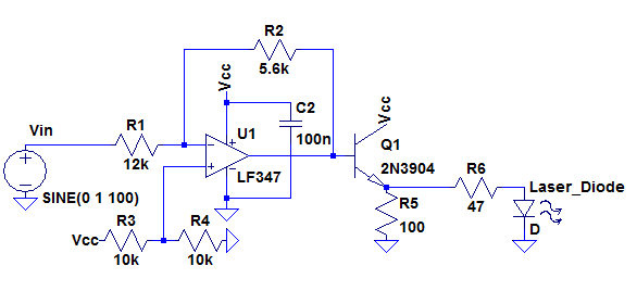 Receiver DesignTo start, we will want to get measurements of the resistance of the photoresistor. I started by just reading the values in some arbitrary locations. No light >2 Meg ohm(my DMM read open circuit) Full Sun675 ohm Room light36k ohmI then set up the laser and my photoresistor in my alignment setup. I then took some more measurements. Because these will vary with the distance, laser aperture, laser wavelength, laser power, and other conditions, I strongly recommend generating your own results. Laser Voltage (Volts)Resistance (ohm) 0(room light)172k 4.0911 4.1842 4.2817 4.3775 4.4748 4.5718 4.6709 4.7692 4.8657 4.9648 5.0633Graphing the values helps to see that it's not perfectly linear, but reasonably close over this small range of values. 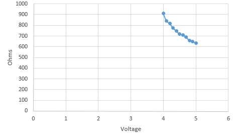 To design the receiver I'm going to make a voltage divider using the photoresistor. I will then connect that to the input of an inverting amplifier. The inverting amplifier output is then passed into a highpass RC filter with a cut off of 10 Hz, this will remove the DC component without any major effects on the audio quality of the system. To select the second resistor for my voltage divider, I looked at my measurements of the photoresistor and choose the value that was closest to the 4.5v measurement. That gave me a values for R7 of 680 ohms, I could then use that to solve for was would likely be my max and min voltages. That gave me a voltage that would voltage ranging from 3.84V to 4.37V, a swing of 0.82V. For the gain stage, I would need a gain of 2.4 to regain my original 2V input. Because of the poor rise and fall time of the photoresistor, I gave myself some extra gain and built a stage with a gain of 3.6, then began testing and quickly decided to up the gain further to 5.4, a much higher gain than expected.
Any design of a variable gain could be used as the receiver: you could use a transistor gain stage an op-amp, or some other method of detection. Now to test the system. I used my function generator to provide a sine wave as the input, and then measured the output of the receiver. As expected strong frequency dependence was found, with -3dB corners of about 20Hz and 550Hz
0 Comments
|
AuthorWrite something about yourself. No need to be fancy, just an overview. ArchivesCategories |
 RSS Feed
